
Beyond Spring Theory: A Quantum of Realism
Deriving the Real Constraints of Mainsprings and Dissecting Defossez's Dead End

How you actually design a mainspring barrel and why the engineering design is richer than the textbook suggests.
SJX Watches has long been one of the few mainstream watch publications to publish genuinely technical content. The equation heavy recent piece on mainspring dimensioning and barrel packing is a worthy contribution to that tradition, and genuinely useful for anyone who wants to start understanding what is happening inside a barrel.
What I want to do here is take the theoretical and extend it into how barrel design actually proceeds when you are doing it, inside the constraints of real projects, with real materials and real clients.
The theory frames the space. What follows describes what happens inside it.
The Spring Is The Thing — Despite Not Being Sexy
The escapement and balance are the part of a watch that earns the attention. Rooftop jacuzzi party, it’s attractive and jiggles attractively with an exotic name like Chronergy, Detent, Cylinder, Mudge, Natural, Dynapulse, Constant Force, Robin, Fasoldt, Flamenville, Verge, that goes on press releases and in headlines.
By comparison, the barrel is down in the basement buried under a hefty bridge, any protruding teeth apparently motionless, it rotates very slowly, once every six hours or so. In terms of photographic interest, it is a featureless drum; the so-called barrel.
The fun is only possible because the torque arriving from the engine room at the escape wheel is sufficient to drive whatever intermittent contraption has been selected to keep the party swinging in time.
The finest escapement in the world is hostage to a mediocre barrel (and gear train, but I digress). The spring is the thing. It always was.
The Theory Is Established — The Empirical Gap Is Not
The mathematical framework SJX presents: deriving developing turns N from barrel geometry, establishing the 50% packing result, demonstrating how parameters scale with the geometry, is established curriculum. The industry training covers this material at advanced level, and the underlying derivations appear in Grossmann and in Defossez’s own treatises. it’s explained well and makes it accessible to a wider audience than the textbooks reach, which is genuinely useful.
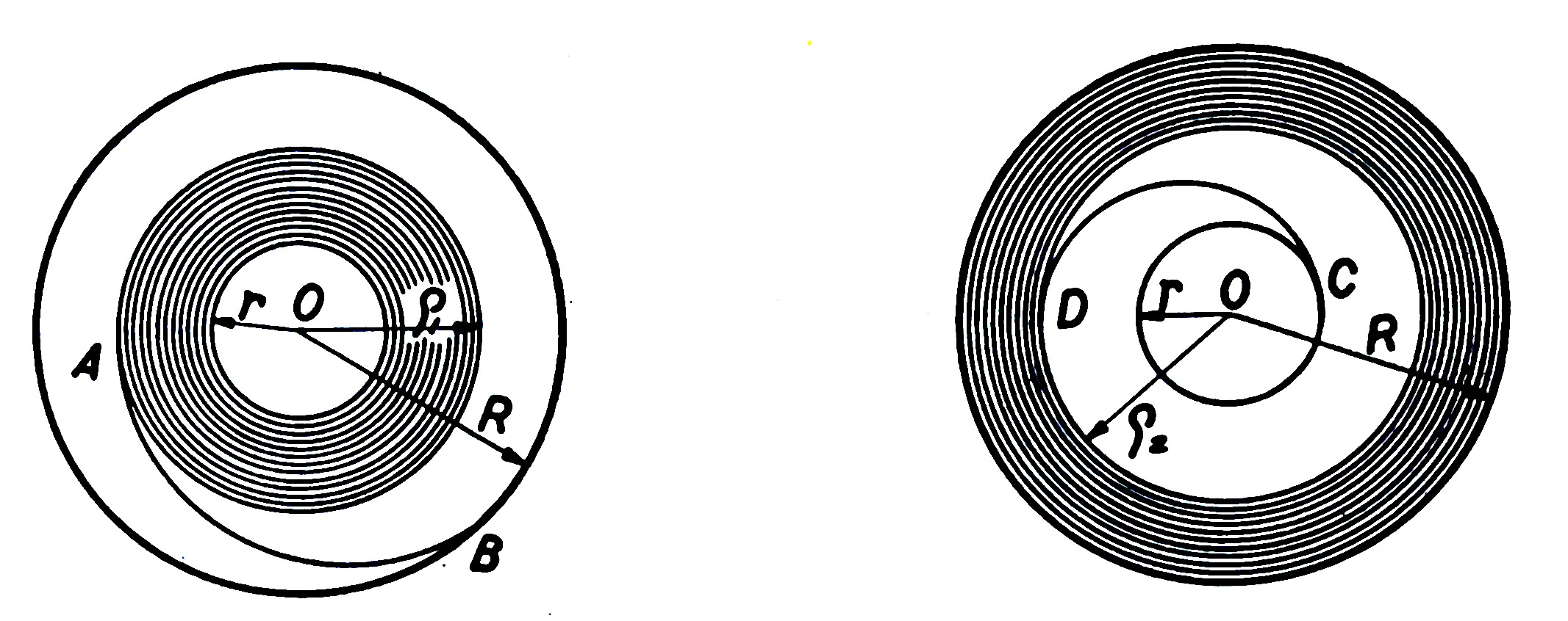
Fully wound barrel (left) and fully unwound (right) ‘r’ is the arbour diameter and ‘R’ is the inner barrel diameter.
But theory describes an idealised barrel in isolation: a perfect Archimedean spiral, uniform coil spacing, frictionless development, no bridle, no lubricant, no serviceability constraint, no client, no shared train ratio from a cost decision made six months ago. The mathematical optimum exists in that clean space. Real barrel design does not.
The empirical gap, the distance between what the equations say and what you actually build, is where it gets interesting.
Your Barrel is Smaller Than You Think — The Wall Problem
With package space set, and target requirements understood, your fundamental barrel size, R, enters the calculation and immediately begins to shrink.
Start with the barrel outer diameter as given by the movement layout. The barrel wheel, the gear engaging the going train, has teeth cut into the outer circumference of the barrel wall. Tooth depth for reliable gear mesh engagement removes material from the interior radius before you have begun. Typically 0.5mm+ of radius disappears here alone.
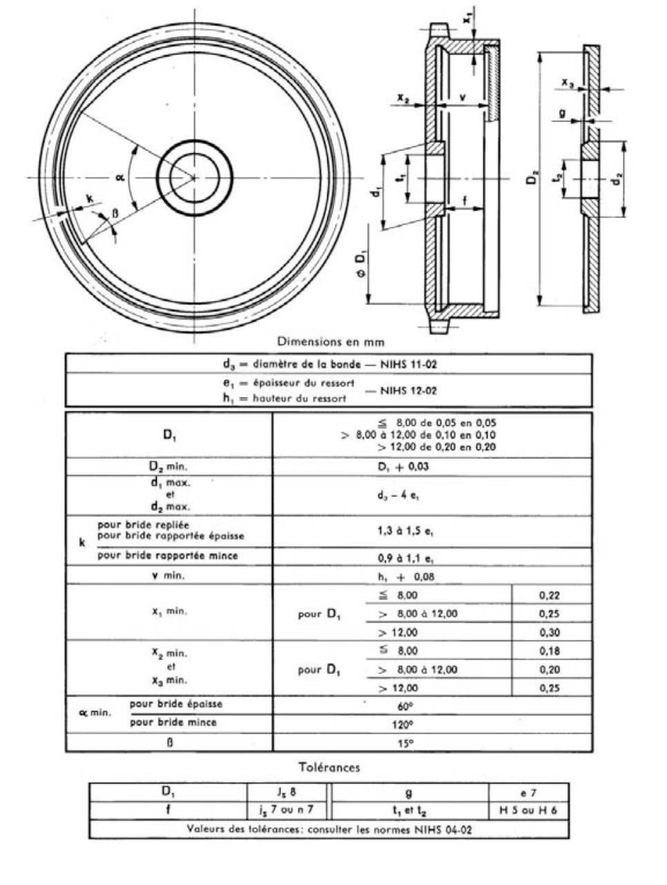
Extract from NIHS standard on geometry for barrels
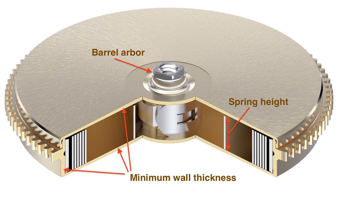
The barrel wall itself must be thick enough to survive the torque load and decades of service. Opening and closing the barrel, pulling the lid on and off, which every watchmaker does routinely at service imposes bending loads on the wall. Below a minimum thickness the wall risks permanent distortion. There are NIHS guidelines that advise on minimum wall thicknesses for precisely this reason.
The barrel floor and ceiling, top and bottom of the drum, must contain the spring under the axial side loads that develop as it uncoils eccentrically and also tolerate service loadings. You can lose 0.5mm total top and bottom.
After all of this, the usable interior radius is considerably smaller than the raw barrel diameter and height suggested. A designer who has not built and measured real barrels tends to underestimate how much R has already been consumed before the spring design begins.
The NIHS guidelines are a starting point. In the very best movements, at the highest level of engineering confidence, they are pushed. There is no more instructive example of what that looks like and what it costs, than the barrel at the heart of the Rolex Chronergy movement.
The Chronergy Barrel: What Rolex Actually Did
In my Chronergy analysis on SJX, I described the barrel in calibre 3235 as the unsung hero of the movement. I won’t repeat the detail, but here is a quick recap.
The barrel walls — reduced to approximately the thickness of one and a half sheets of printer paper at their thinnest — represent a conscious trade of serviceability for capacity. The barrel is available only as a complete sealed assembly for service.
Traditional disassembly and reassembly on a watchmaker’s bench appear, at minimum, materially less attractive than modular replacement; the geometry strongly suggests a much narrower margin for conventional bench handling. That looks less like an oversight than a conscious service-model trade-off.
The arbour sits at its practical minimum for the spring alloy specified. The spring thickness was estimated to have been reduced by approximately 9% from the preceding calibre; recovering barrel cross-section for additional turns while accepting a torque reduction that the Chronergy escapement’s efficiency improvement could absorb. The barrel cap is further tapered between arbour and outer circumference; not for aesthetics, but to allow the lid enough flexibility for a reliable snap fit while maintaining structural integrity at the critical wall sections.
What Rolex demonstrated is that the NIHS guidelines are not physical laws. They are engineering recommendations calibrated to the service infrastructure of the industry. A manufacturer who redesigns that infrastructure and has the volume to make proprietary service economics viable can operate well beyond them. The penalty is real: traditional serviceability is materially reduced. The gain is also real. Whether that trade is right for any given movement at any given price point is a separate question. But the Chronergy barrel represents the frontier of what barrel design looks like when the constraints are treated as variables rather than limits. Whether as extreme in design or not as Rolex, more and more manufacturers simply now provide drop-in new barrels for service.
How Small Can the Centre Go — The α Question
The arbour diameter is the pivot of the whole design. The more tightly curved the centre can be, the more interior volume it unlocks for more spring: more turns or a thicker spring. The question is how far you can go. The answer requires understanding three separate physical phenomena operating at different scales.
What Defossez’s Guideline Actually Was
Léopold Defossez, whose major horological treatise was published in the early 1950s (I can recommend for your horological bookshelf) gave the watchmaking world the guideline α = r/e ≥ 16 as a practical floor below which springs fractured during manufacture. It was calibrated empirically to the spring steels and manufacturing processes of his era. It was not derived theoretically from elastic mechanics, even though that was the vocabulary he used to describe it.
That vocabulary was the best available. Fracture mechanics as a practical engineering discipline was being assembled in real time as Defossez wrote. Griffith’s foundational crack energy theory of 1921 had been largely ignored by practising engineers for three decades. Irwin’s stress intensity factor framework appeared in 1957 after Defossez had published. Paris’s law for fatigue crack growth rates came in 1961. Defossez reached for the language he had, which was elastic stress theory, and it pointed at the right number even though the mechanism it described was not the governing one.
Here was a practical engineer with a practical guideline. The guideline was right for the time. The complete explanation had to wait for the science to catch up. Today, if you have the budget for the material, we are happily at α = r/e ≥ 10.5.
To give you an idea of how significant that is it’s an arbour diameter as little as 2.5mm versus one nearly as much as 4mm.
Why Springs Used to Break — and Why They Almost Never Do Now
To understand why Defossez’s number of α = 14 to 16 was right for his era, and why we can now push to α = 10.5, you need to understand what actually happens to a mainspring when it is manufactured. It is considerably more violent than you might expect.
When a spring is made, the strip of metal is wound tightly onto a cylindrical mandrel, essentially a metal rod, at approximately the arbour radius. This bends the metal far beyond its elastic limit. Think of the elastic limit as the point at which a material stops springing back and starts permanently deforming. For best specification modern spring steel, the forming process imposes a bending strain of 4–8% depending on the spring thickness and arbour size. The metal is being bent beyond the point at which it would normally yield permanently.
This is not a manufacturing defect. It is the intended condition. Every mainspring that has ever been made was formed this way.
The question is not whether the metal deforms permanently, it always does. The question is whether it has enough ductility (enough capacity) to absorb that deformation without cracking. Think of ductility as the difference between plasticine (very ductile — you can deform it enormously without it breaking) and chalk (brittle — it snaps with very little deformation). Spring steels sit somewhere in between, and exactly where they sit determines how small you can make the arbour.
The governing rule is simple:
Minimum α = 1 ÷ (2 × fracture strain of the material)
For 1950s spring steels, the fracture strain in bending can be treated as about 3%. Plug that in: minimum α = 1 ÷ (2 × 0.03) = 16. That is where Defossez’s number came from. It was not derived from elastic theory. It was the experimental floor below which springs cracked on the mandrel during manufacture. He described it in elastic language because fracture mechanics, the branch of engineering that explains cracking properly, had not yet matured into a practical design framework available to watch engineers when he was writing in the early 1950s. The correct mathematical framework for crack propagation only appeared in the late 1950s and 1960s, after Defossez had published.
Modern Nivaflex alloys, the cobalt-nickel-chromium spring materials used in high-quality Swiss watches today, can sustain materially tighter bending before cracking. The same formula with them gives α values around 10.5 as modern high-grade practice.
The improvement is not simply that modern alloys are stronger. It is that they are cleaner at the microscopic level. Spring steels crack because cracks start at tiny defects inside the material; small particles of oxide, carbide, or slag left over from the smelting process. Modern production methods, specifically vacuum induction melting followed by vacuum arc remelting (VIM+VAR), remove the vast majority of these particles. Fewer defects means the material can bend further before a crack starts, which means the arbour can be smaller, which means more spring fits in the barrel.
One final manufacturing point that matters: the spring must always be formed before it is age-hardened. Age hardening is a heat treatment process that raises the strength and hardness of the alloy significantly, but it also reduces ductility. If you tried to form the spring after age hardening, the reduced ductility would cause it to crack on the mandrel. So the sequence is always: form the spring first while the material is still relatively ductile, then age-harden it to get the service strength. This is not a trivial detail. It is the only way to simultaneously achieve the tightest forming radius and the highest in-service performance.
Why Winding Your Watch Does Not Re-Bend the Spring to Its Limit Every Time
Here is something that surprises most people when they first encounter it: winding your watch does not subject the innermost coil of the mainspring to anything like the strain it experienced during manufacture. Not even close.
During manufacture, the spring was bent beyond its elastic limit. During normal service winding, the innermost coil moves between two positions: its natural resting shape (the formed radius) and the arbour radius when fully wound. That is a much smaller excursion, the spring has already been permanently set to approximately the arbour radius during forming. The winding process is moving it through a modest range around a shape it has already been forced into permanently.
After the first few winds, something important happens. The spring settles into a stable pattern where the service winding and unwinding cycle stays entirely within the elastic range and below the point at which the material would permanently deform again. Engineers call this elastic shakedown: the structure has shaken down from its initial plastic state into a regime of purely elastic cycling. It bends and springs back, bends and springs back, without accumulating any further permanent deformation.
Think of it like this. Imagine bending a paperclip back and forth. The first large bend permanently deforms it — that is forming. After that, small back-and-forth movements within a modest range do not permanently deform it further — that is elastic shakedown. The paperclip is not re-yielding on every small cycle. It is just flexing elastically within the range the first big deformation established.
For modern Nivaflex spring alloys, the threshold for remaining in elastic shakedown is very comfortably met under normal service winding conditions.
This means the spring is not normally being driven back into gross plastic deformation during service winding. In a correctly specified modern spring, the service cycle is predominantly elastic, which is why routine winding is not in itself the usual failure mechanism.
For the older spring steels of Defossez’s era, the same calculation was much less comfortable. At tight α values, service winding could push the innermost coil back into the plastic zone accumulating a small amount of permanent damage on every wind. Over thousands of winds, this added up. Springs wore out. They needed replacing as a routine service item. The conservative α = 16 was partly about surviving manufacture and partly about keeping the service cycling within a tolerable range for materials that could not achieve true elastic shakedown at tighter geometries.
What this means for the modern watchowner is important: a correctly specified modern mainspring, running in elastic shakedown, does not accumulate fatigue from normal winding. If it breaks, the cause is usually not the mere fact of normal winding. It is a defect in the material, a microscopic inclusion or surface irregularity that grew into a crack over thousands of cycles, invisibly, until the remaining cross-section was too thin to carry the load and failed suddenly. The sudden fracture is dramatic. The damage that caused it was quiet, slow, and usually not a consequence of normal winding behaviour itself.
The Torque Formula — Why not e³
Pure beam theory, read naïvely, points you towards an e³ dependence. Use that without correcting for barrel geometry and you will not design a successful watch movement. The formula we actually use needs explaining.
The remainder of this article is exclusive for Founding Tier for a week, then to paid subscribers thereafter.